The first-generation highlander hybrid had some problems with the inverter. The 2006, 2007, 2008, 2009, 2010 models were affected, and Toyota issued a safety recall and replaced the IPM (part of the inverter) at no cost to the owner.
ONLY ONE FREE FIX PER CUSTOMER
Most of the time when we see a problem with a Highlander inverter, the owner was not aware of the recall and we refer them to a dealership for a free repair. However, this car already had the recall performed, and Toyota won’t perform the repair again for free.
Also, this Highlander had a P0A79 with information codes 698 and 672. These are codes for a different IPM for the rear motor/generator, but the recall only addresses the IPM for the front motor/generators. Our customer wanted us to take take the inverter apart and see if there would be any way to fix it short of replacing it.
Removal and inspection of the inverter
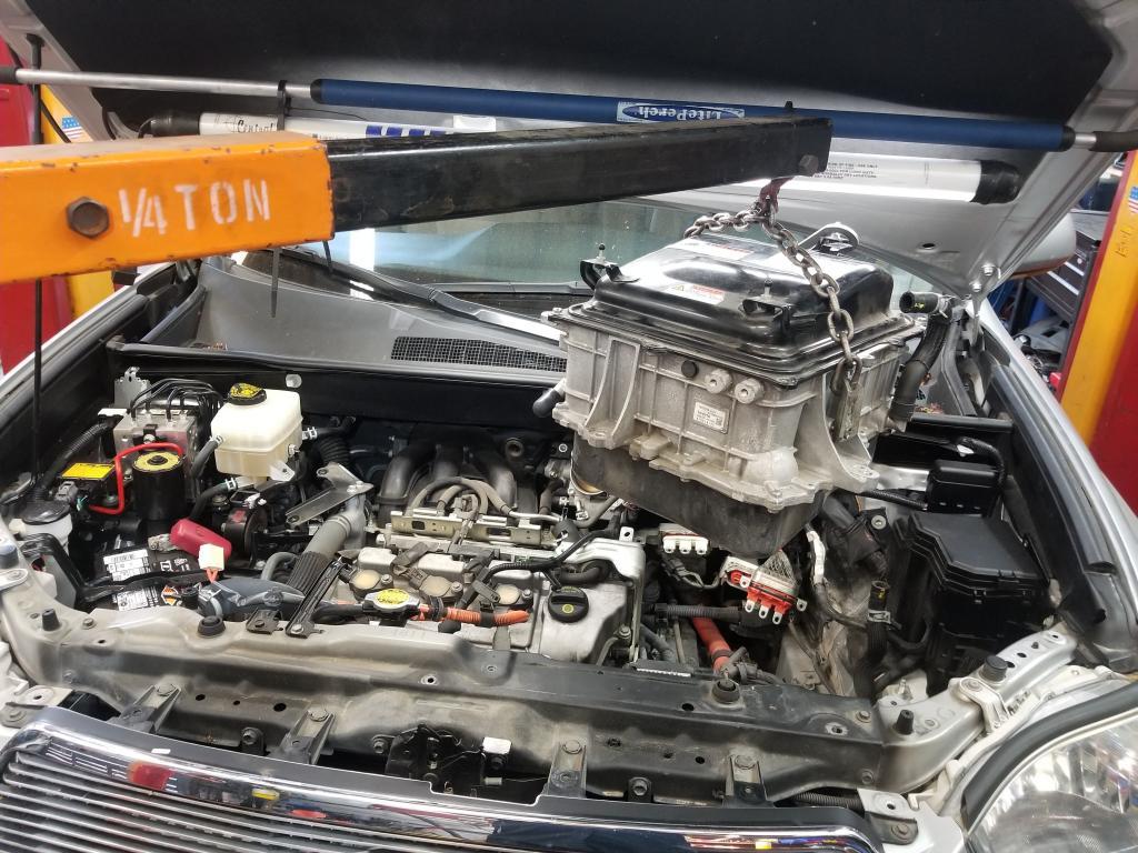
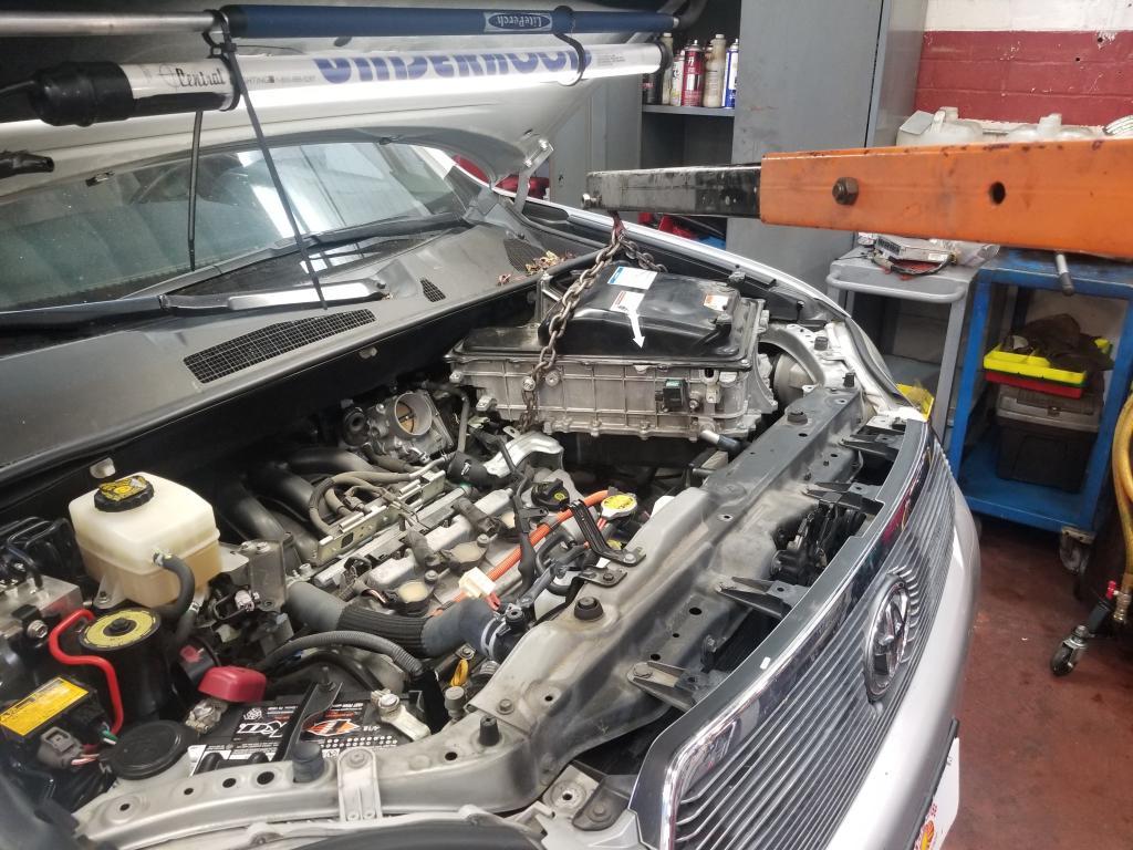
On a Prius I’ll just unbolt the inverter, disconnect the hoses and electrical connections, and lift the inverter out of the car. The Highlander has a big heavy inverter and it’s a tight squeeze out of its spot in the engine bay so I decided to save my back and use the engine hoist.
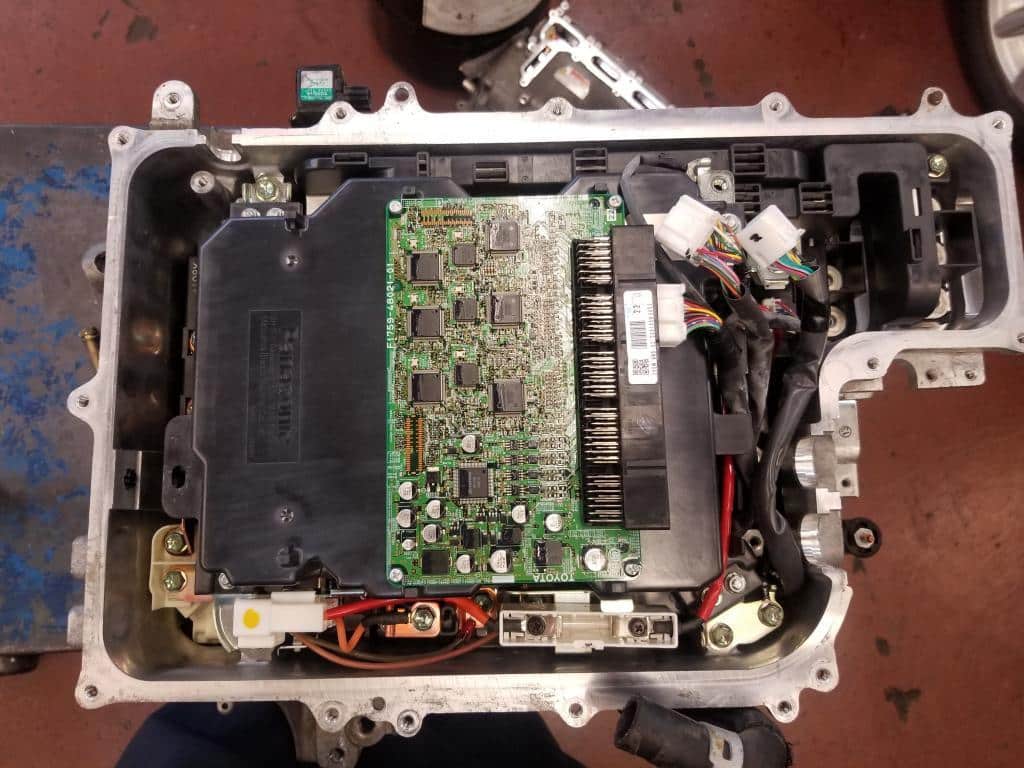
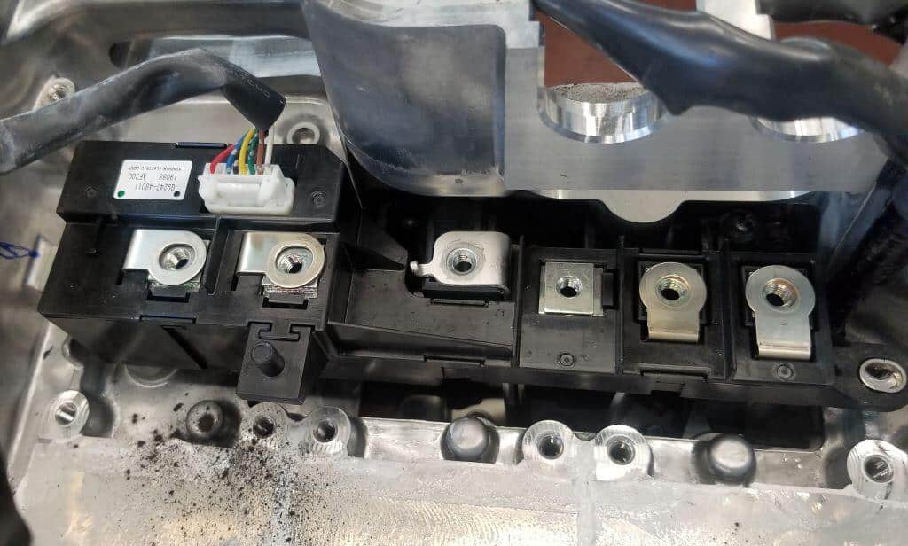
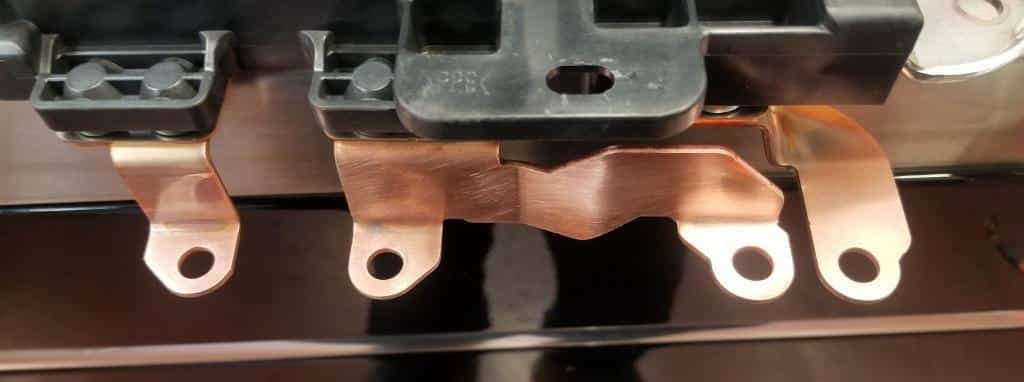
After a little bit of disassembly the problem was pretty obvious. The picture below shows one of the terminals of the IPM discolored from overheating. The burnt terminal is one of the three terminals leading to the larger of the two electric motors, the MG2. This is the IPM Toyota replaced under recall. I suspect that the bolt wasn’t torqued properly, since this is presumably the new version of the IPM that doesn’t burn out.
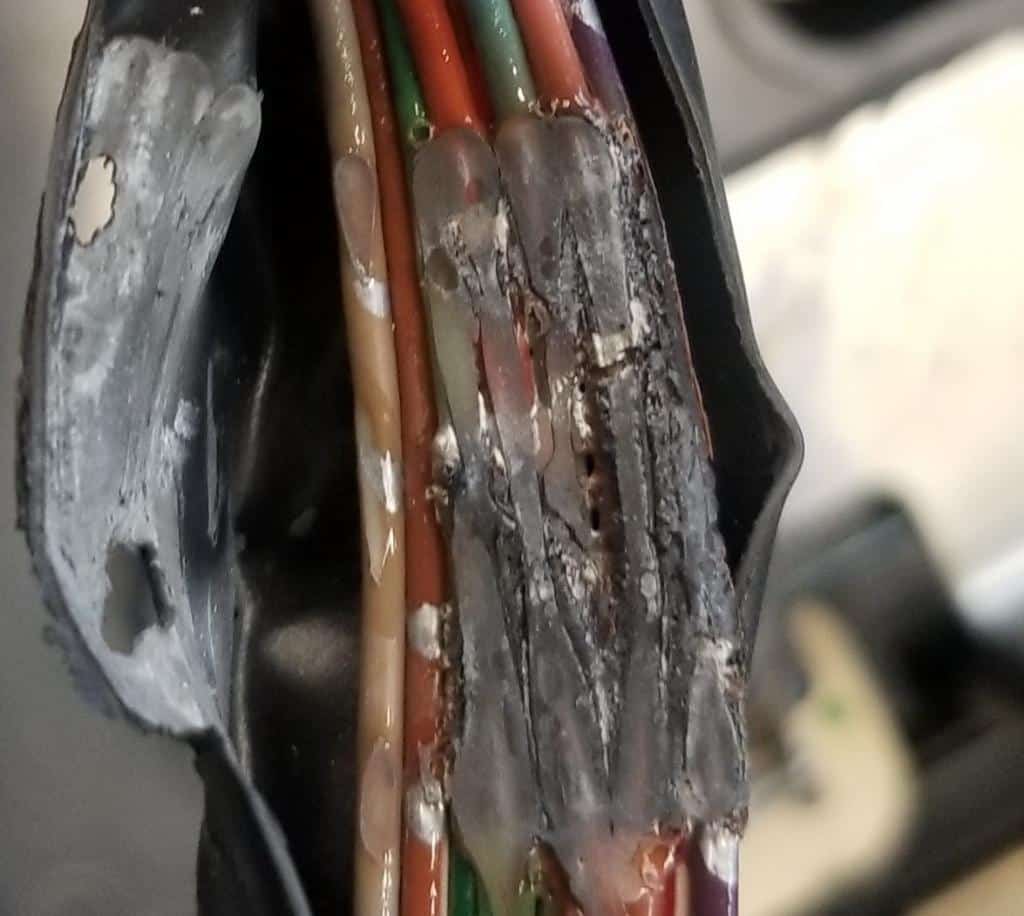
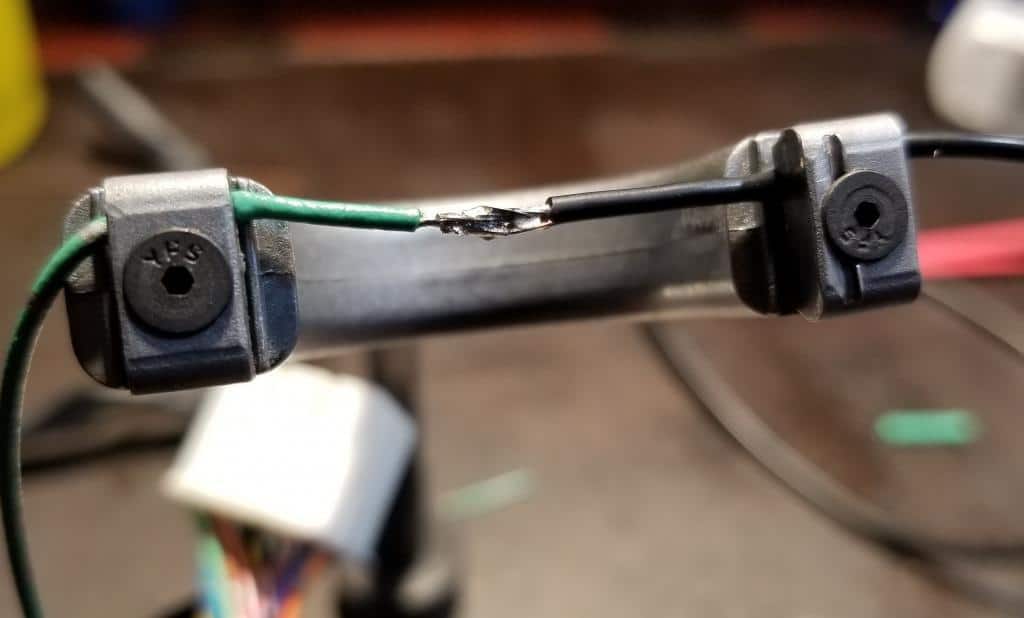
The harness goes to the IPM for the rear MG (motor/generator) for the 4-wheel drive. The hot terminal melted through the conduit and insulation for the wires inside, causing them to short together.
The transistor set that controls the rear differential electric motor is completely unscathed. The reason for the rear IPM codes is damaged wiring, not a problem with the MGR IPM.
YOU CAN’T BUY THIS PART OF THE INVERTER
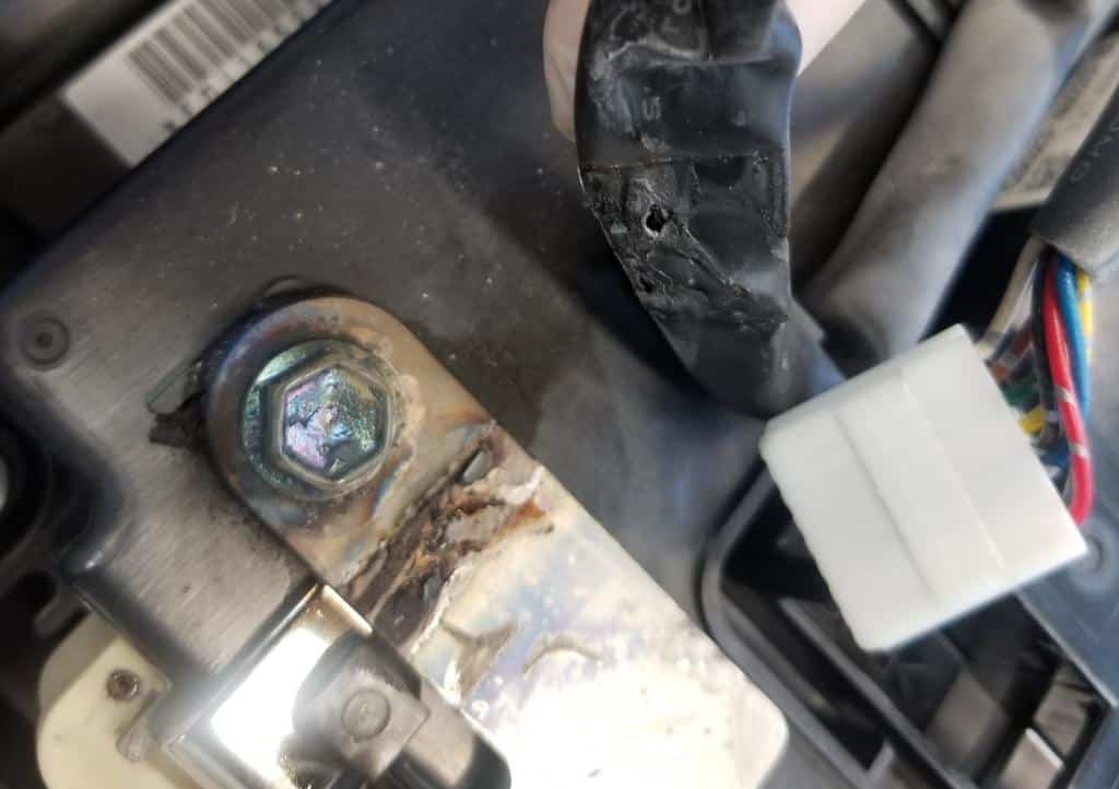
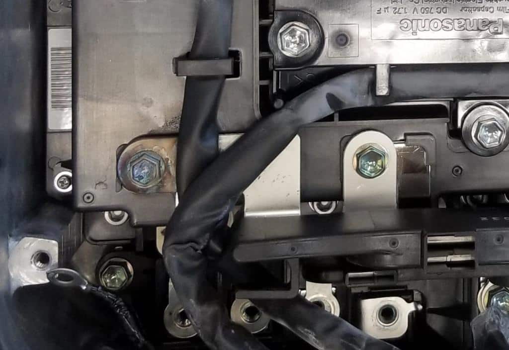
This is the transistor terminal is suspect wasn’t properly torqued when the IPM recall was performed. A loose connection is going to create resistance, and resistance is going to create heat. The harness that runs right over the top of the terminal got pretty toast and melted, causing the wires to short together.
The harness isn’t available separately, so repair is the only option short of replacing the entire inverter. The inverter is $8225, which makes repair an appealing option.
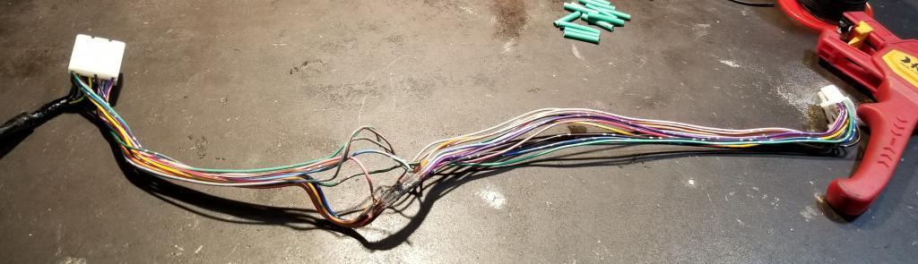
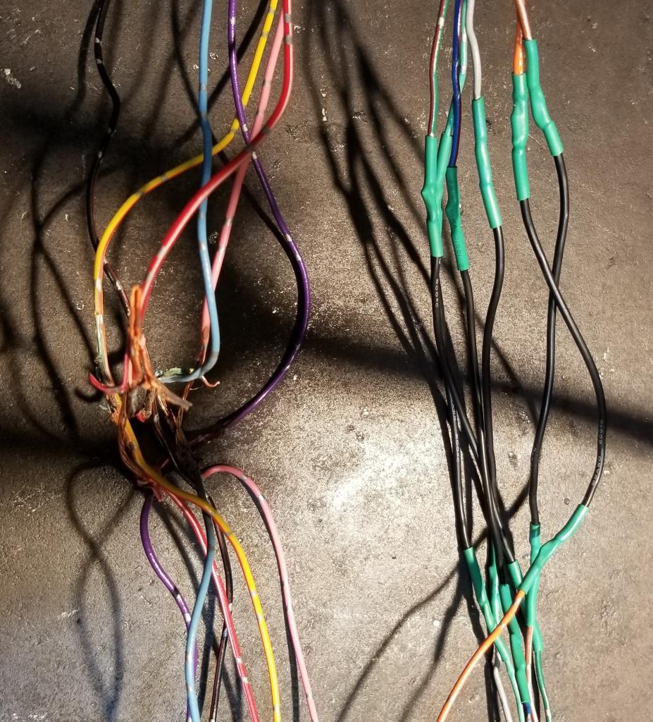
I stripped the wires back until I found un-oxidized copper wire, and then soldered in marine grade fine-strand wire with silicone insulation. Silicone insulation is very resistant to heat, but if this repair works out the wires shouldn’t be getting hot anymore. The nifty holder pictured below has a magnetic base and is one of my favorite tools.
SOLDERING A LOT OF WIRES ALWAYS TAKES LONGER THAN YOU THINK IT WILL
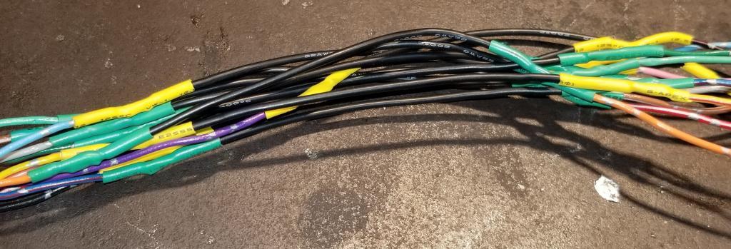
There are 12 wires in the harness, so the harness needs 24 solder joints and 24 heat shrink covers. Moving quickly with all the tools in front of me, it took about 3 minutes per joint to strip, set up, solder, and heat shrink each one. It’s easy to underestimate the amount of time a job like this will take because it seems so easy, but 3 minutes x 24 joints is about an hour and quarter, not including setting up and breaking down or any errors (like forgetting to put the heat shrink on the wire before soldering!). Anyway, my point is that every time I see a project like this I think, “ah, that’ll take about 15 minutes,” and then I end up working unpaid for an hour and a half!
COPPER OXIDE ISN’T CONDUCTIVE
So the harness is now repaired, but the root cause of the failure still needs to be fixed. My theory is that the IPM terminal bolt wasn’t tightened fully during the recall. I think the IPM is still OK, because the car drove in reverse before I took the inverter apart. This means that the IPM and MG2 were working. However, the contacts are badly oxidized. Oxidized copper doesn’t conduct current well. I scraped the oxidation to reveal fresh copper and ensure a good connection.
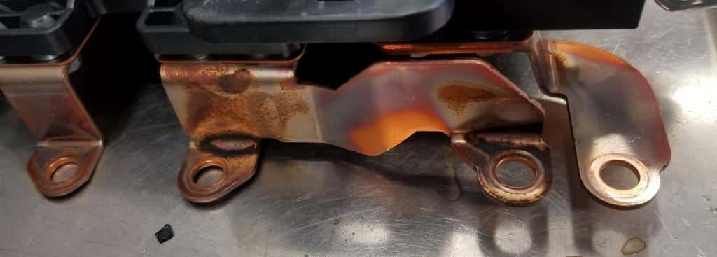
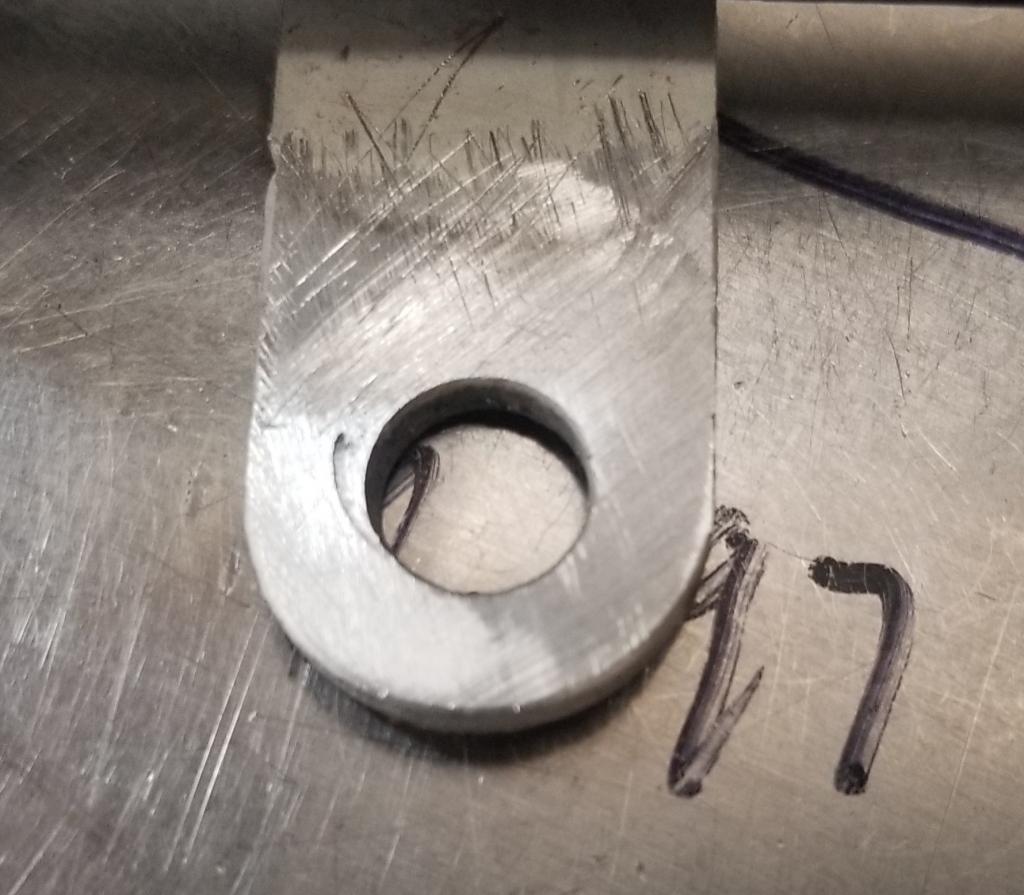
The terminals for the MG2 IGBT are folded over captive nuts mounted into the plastic. The captive nut got very hot and melted into the plastic, so the captive nut was no longer secured. The nut spun with the bolt, which made it difficult to remove. I bent the terminal away from the IGBT and then held the nut with a wrench. Once removed I was able to remove the galling, burnt plastic, and oxidation by scraping with a flat carbide tool.
INVERTER MASK
Now that all the damages are repaired, it’s time to reassemble the inverter, but there’s a problem. The IPM is attached to a liquid-cooled heat sink built into the inverter case. To increase the thermal transfer between the IPM and the inverter, a thermal transfer grease is applied to the IPM. Toyota requires the grease be applied in specific locations on the IPM and a specific layer thickness. To facilitate the correct application of grease, Toyota supplies a mask to apply grease to the IPM in the correct location and film thickness. But here’s the problem, Toyota doesn’t sell the mask separately from the IPM. I called our local dealership to see if they might have an inverter recall in the shop so I could get the mask after they were done with it. No such luck. Time to get creative.
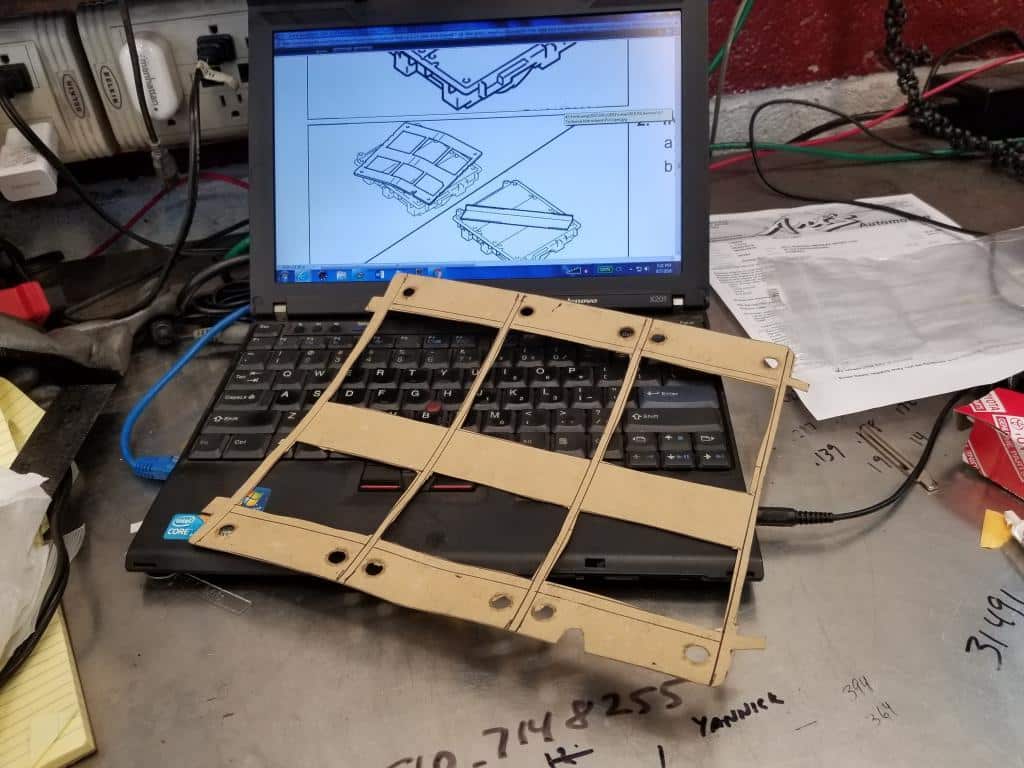
The service manual has a picture of the mask, and I have gasket paper and some spray tack. If someone is out there about to do the same thing, use something non-porous and more like plastic. Gasket paper sheds fuzz that gets into the grease. Anyway, the measurements are unknown, but we have inverter for size and the picture for proportions. It’s probably pretty close.
OOPS
As far as the thickness goes, I missed it on the my first try. How do I know? Well, Toyota specifies that two tubes should cover the entire area. Using my first mask two tubes covered about 1/3 of the area, so it was obviously too thick. I reduced the thickness of the mask to what I thought would be appropriate. After buying two more tiny tubes of grease for $50 each, I gave it another try. I got lucky with my 2nd attempt. Two tubes was just enough to cover all the area with only a tiny amount of excess.
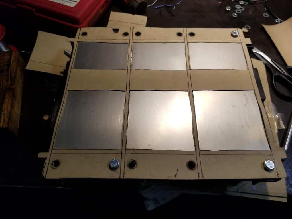
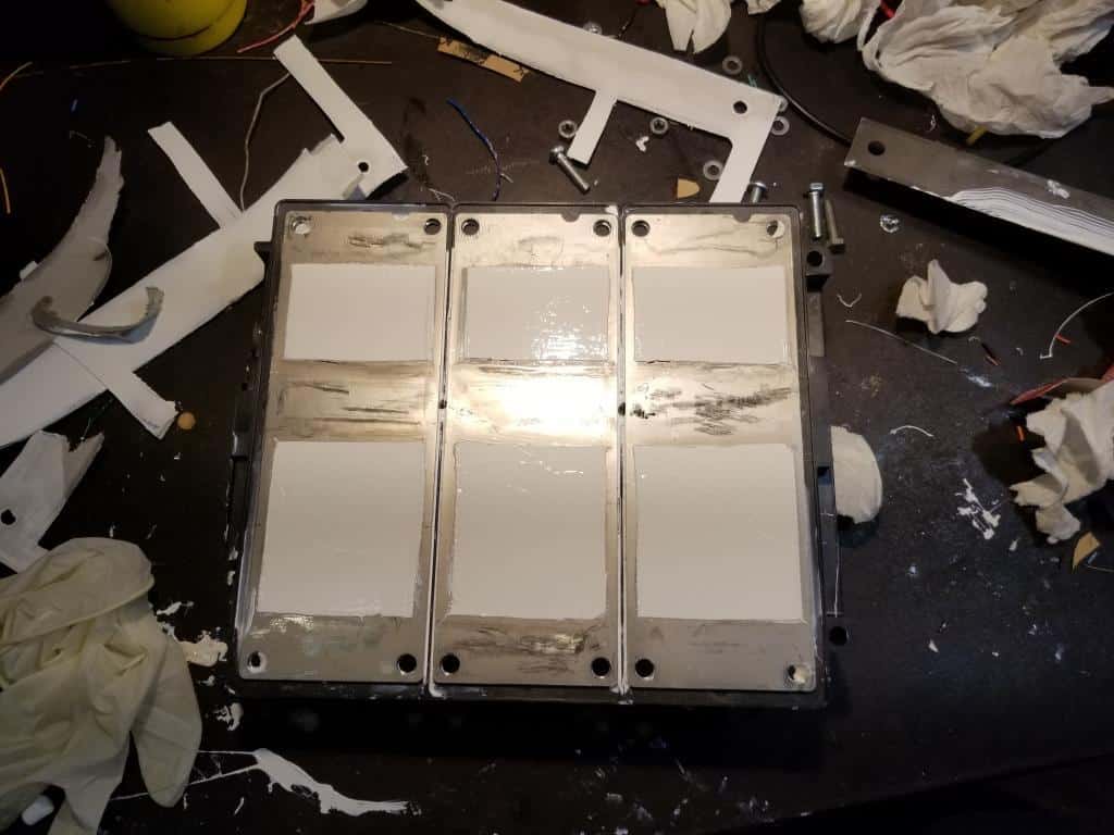
Not exactly clean-room conditions I know, but this is how it looked in real life after two attempts. Had I needed to make a 3rd mask, I no doubt would have cleaned up and ended up with prettier pictures.
IT’S BEGINNING TO LOOK LIKE AN INVERTER AGAIN
After reassembling and installing the inverter, everything worked normally! As of 8/10/18, it has been working for a couple of months and I have high hopes that it will keep going. The final bill for the diagnosis and repair was $2096. Originally the customer had the car at the dealership where they said he needed a new inverter and quoted just under $10,000. Technically they were correct, but sometimes, if a customer is willing to accept the risk, things can work out well in the end.