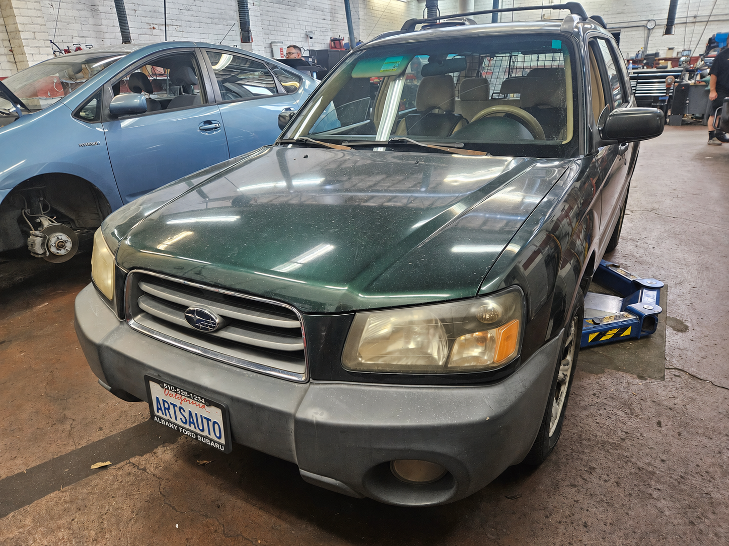
This 2004 Subaru Forester came in without any reported cooling-system symptoms. It was due for a smog inspection, and during our inspection we found a P0483 — Cooling Fan Rationality Check code.
This isn’t going to be a particularly common repair. There aren’t nearly as many 2004 Foresters on the road as there used to be, and this was a high-mileage car with what was probably an unusual ECM failure.
However, the diagnostic process is useful because the same basic techniques apply to just about any electrical system.
What does P0483 mean?
P0483 doesn’t simply mean “bad cooling fan.” The ECM runs the cooling fans and watches what happens to engine temperature. If the temperature doesn’t drop as expected with the fans operating, it sets the code.
We had another concern as well. The engine had overheated at some point and the cooling system was about 3/4 gallon low on coolant. The missing coolant may have boiled out during the overheat, or there may be another cooling-system problem. More on that later.
For now, we had an obvious fault to diagnose: the cooling fans didn’t work correctly.
Start by checking how the system is supposed to work
Subaru provides a test mode that cycles the cooling fans through:
LOW → HIGH → OFF
Both fans worked on low speed, but when the system should have switched to high speed, both fans shut off.
That already tells us quite a bit.
Both fan motors work. The system has enough power and ground to operate both motors. The ECM can also operate at least part of the fan-control system.
So rather than testing everything from one end to the other, we started near the middle.
Divide the circuit


The Forester uses several relays to change the way the two cooling fans are powered. One of them is called the fan mode relay.
We removed the relay and bypassed the appropriate load terminals.
One fan immediately ran at high speed.
That’s a very useful test. In a few seconds we’d proven the fan motor and most of its high-current circuit without individually testing every wire and connector.
We then bypassed the sub fan relay.
The second fan ran at high speed too.
Now we knew there wasn’t anything fundamentally wrong with the fans or their high-speed power circuits. The problem was on the control side of the relays.
This is one of my favorite ways to approach electrical diagnosis. Find a convenient point near the center of the system and test from there. The result tells you which half of the circuit deserves your attention.
There’s no point spending twenty minutes testing things you’ve already proven in twenty seconds.
Two bad relays? Probably not
The fan mode relay and sub fan relay both receive battery voltage on one side of their coils. The ECM turns them on by grounding the other side.
More importantly, both relays are controlled by the same ECM output: connector B134, terminal 13.
Both relay coils had power.
With high fan speed commanded, however, the ECM-controlled side of the coils measured about 8.6 volts.
That’s wrong.
When a low-side driver turns a relay on, it should pull the control side of the coil close to ground. Seeing 8.6 volts meant current wasn’t flowing through the coils as it should.
There were two likely possibilities:
- excessive resistance between the relays and the ECM
- a failed or weak output driver inside the ECM
Time to find out which.
Don’t condemn an ECM before testing the wires
If a wire tests bad with an ohmmeter, it’s bad. If a wire tests good with an ohmmeter it doesn’t mean anything.
A wire with only a few strands remaining may show nearly zero resistance with an ohmmeter but still be unable to carry enough current to operate a load. Connector terminals can cause the same problem.
We tested the control wiring between the relay coils and ECM under load.
It was good.
We also tested the ECM grounds.
They were good too.
At this point the evidence was pointing squarely at the ECM.
Unfortunately, a replacement ECM was roughly $1,200 and was no longer available from Subaru.
Fortunately, an ECM is just another electronic circuit.
Finding the failed driver inside the ECM
Once the ECM was open, we needed to figure out which component on the circuit board controlled B134 terminal 13.
You can sometimes follow circuit-board traces visually, but it’s often easier to let the meter do the work.
An ohmmeter with a continuity beeper — or a meter’s diode/continuity mode — is handy for this. Put one lead on the ECM connector terminal and probe likely components on the circuit board.
The beep lets you trace the circuit without constantly looking back and forth between the meter display and the board.
Following B134-13 into the circuit board led us to its output driver.
We replaced the failed driver and reassembled the ECM.


Did it work?
Yes.
With the repaired ECM installed, Subaru test mode now cycled the cooling fans normally:
LOW → HIGH → OFF
Both fans operated at full speed when commanded, and the control circuit worked exactly as it should.
A $1,200 unavailable ECM became a repairable circuit board instead.
A few diagnostic lessons
This particular failure probably won’t help thousands of people fix their 2004 Foresters. But the diagnostic process applies to much newer cars.
Understand the system before testing it
Knowing that both fans should operate at low and high speed immediately gave us a useful symptom. “The fans work” wasn’t good enough. They worked in one operating mode and failed in another.
Start somewhere useful
You don’t always need to begin at the battery and work toward the load, or start at the ECM and work outward.
Bypassing the fan mode relay divided the system and quickly proved a large portion of the circuit.
Test wiring under load
Continuity is useful, but it doesn’t prove a circuit can carry current. When a voltage reading suggests excessive resistance, load the circuit before blaming the control module.
Control modules can be diagnosed too
Once the external wiring and grounds were proven good, the ECM wasn’t a mysterious black box anymore. We knew which terminal wasn’t doing its job, and an ohmmeter helped us follow that circuit directly to the component responsible for driving it.
Sometimes replacing a control module is the practical repair.
Sometimes replacing the part inside the control module makes more sense.
In this case, it worked perfectly.