If you’re curious about what’s involved when mechanics rebuild hybrid transmission systems, this article covers the process and issues we have encountered. You’ll learn about diagnosing common hybrid transaxle problems, such as high-voltage leaks and shorted windings, and get a detailed look at the technical steps involved in disassembling, inspecting, and rebuilding components like the Motor/Generator unit (MG2). This guide is intended for other mechanics or curious vehicle owners who to learn more about rebuilding a hybrid transaxle.
Trouble code P3125 caused by failed MG2 stator windings were some of the first hybrid failures we encountered in the early 2000s. Back then it was all new to us, and diagnosis was a challenge. Often the Toyota trouble trees will lead to an incorrect diagnosis of the inverter.
Luckily for us, we know some of the best hybrid trainers, mechanics, electrical engineers, and we even have a few contacts with high-level Toyota folks. These contacts prevented us from making mistakes in the early days. It’s good to have smart friends!
Hopefully this page will help some folks in industry out as well as being informative for our more curious customers.
Motor diagnosis has become a lot easier for us since the early days. We now have many methods of testing stators, including some very advanced equipment typically used for industrial motor testing. However, there is more than one way to find stator problems. Some methods only require equipment that many shops will already own.
How can you tell if the MG2 is bad?
The first clue the MG2 is shorted is usually a judder on acceleration, sometimes without a master warning indicator. This judder feels a lot like a misfire, but a misfire can be easily eliminated by accelerating in reverse. In reverse, MG2 is providing 100% of the motive power, so an engine misfire is eliminated as a possibility.
If you’re “lucky” enough to have this symptom, odds are that the MG2 is the source of your trouble. However, if you plan on fixing the car, it’d be wise to be absolutely sure before investing in an expensive repair. My philosophy is to always verify a diagnosis in at least two different ways. This article will focus on phase to phase and turn to turn shorts. The MG2 can also fail in several other ways —
- a phase to ground short
- rotor failure
- bearing failure
- resolver failure
- temperature sensor failure (although almost never as an isolated failure)
I’ll be ignoring all of these failures today. I suspect this article will be much longer than most people will have the endurance to read as it is. The key element of stator testing is this: all of the phases should be equal. If you remember only one thing from this article, remember that all phases should be equal.
Equal what? Well whatever test you’re performing the results should be the same on every phase because the phases are the same — the same length of copper wire and the same winding pattern, therefore whatever test you perform on one phase should yield the same result as on any other phase.
Methods of testing stator windings
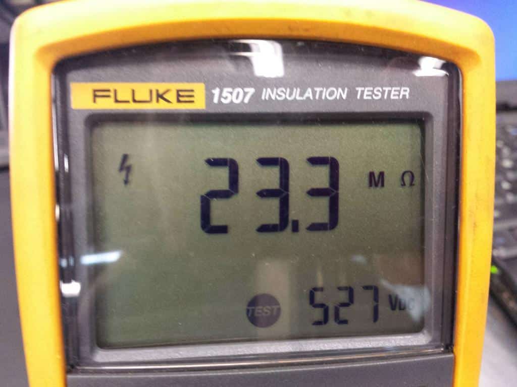
Megger (Insulation test meter)
I’ll start with the most common method of testing: insulation resistance testing. This type of testing is designed to find phase to ground shorts, which I said I wouldn’t be covering, but this is an important test and a good place to start. Also, a lot of phase-to-phase shorts are caused by two phases shorting to the back iron.
Insulation testing is performed with an insulation resistance test meter, also known as a megohmmeter or “megger”. The last two names are trademarks, sort of like Kleenex is to facial tissue.
An insulation resistance test meter measures very high resistance in megohms. One megohm is one million ohms. Hybrid and electric vehicles are never chassis grounded, which is sometimes hard for technicians familiar with 12V chassis-grounded electrical systems to conceptualize.
A quick and easy check
Anyway, checking for a ground isolation fault is the easiest of all of the motor tests, and is a good way to start. If the motor fails quick and easy test, there’s no reason for further testing.
Theoretically, a ground isolation fault would cause a P3009 or P0AA6 in addition to the P3125 though. A megger test is simple: connect one lead to the transaxle case and one lead to one of the phases, press the test button and look at the reading. Which phase should you connect to? It doesn’t matter. One phase is as good as another. Why? All phases are tied together and the resistance of the phase windings only add milliohms to test being performed in megohms; if the short to ground is on the U phase and you are testing the V phase, the megohmmeter will be the same as if you had been testing U phase.
The only exception is if there is an open in one of the windings, which is pretty rare. If you’re worried, just repeat the test on the other two phases.
Back to the P3125
OK. Back to the P3125. The information code 287 indicates “an internal inverter short” per the manual, but if you read between the lines, 287 sets when the current flow is excessive. If you think about it, what’s more likely, the low resistance in the load or a short between two IGBTs? (IGBTs are just large transistors that can handle very high current.) Of course the load is the more likely culprit. In this case, the load is the MG2.
The information code 303 indicates a fault with the current sensor. Here’s an excerpt from the manual —
“DTC P3125 − Information code 291, 293, 295, 299, 301, 303 — The HV ECU detects the malfunction of the motor inverter current sensor. It detects the malfunction of the sensor system, not of the high voltage system.”
I think this is a case of “playing telephone” where information is lost or misinterpreted as the engineers communicate with the folks who write the manual.
An OUT-OF-RANGE sensor isn’t always a bad sensor
I think the best analogy for how the 303 can set is to compare it to a coolant temperature sensor (CTS) code that sets when an engine overheats. The CTS is reading out of normal range, but only because the engine coolant temperature is out of range. There’s nothing wrong with the sensor. Say the CTS range is -40F to 230F. If the engine overheats and the coolant temperature reaches 245F, the temperature sensor is now reading out of range, but it’s not because there is a problem with the sensor or sensor circuit, it’s a problem with the actual coolant temperature. The P3125 303 will set for the same reason: there’s a problem with excessive current draw, not the current sensor or sensor circuit. In this case, the service manual is incorrect: a 303 can be caused by a problem with the high voltage system.
Milliohmmeter Testing
The Toyota service manual starts off with milliohmmeter testing. A milliohmmeter is the opposite of a megohmmeter; a milliohmmeter measures very small resistances. If you think about ohm’s law, lower resistance would cause higher current draw, and both codes can be caused high current draw, so measuring resistance seems like a good place to start.
However, it should be noted that the milliohmmeter only measures resistance; it doesn’t measure impedance. Since the winding is an inductor driven by AC power, resistance is only part of the picture.
Impedance is the total effect of resistance and reactance. Reactance is the opposition to current flow caused by inductance and capacitance in the circuit. So, when you check DC resistance, you’re only getting part of the picture. A milliohmmeter is a finicky piece of equipment. It measures very small amounts of resistance. Most components you might test with a milliohmmeter would read 0 ohms with a standard ohmmeter. Because it is so sensitive, it needs to warm up, have very good connections, and the component’s temperature must be controlled.
Adjusting for temperature
Here’s what Toyota has to say about testing:
If the MG1 and MG2 temperature are high, the resistance varies greatly. Therefore, measure the resistance at least 8 hours after the vehicle is stopped. To correct the variation of the measured resistance due to temperature, use the following formula to calculate the resistance at 20°C (68°F).
- R20 = Rt / {(1 + 0.00393 x (T – 20)}
- Rt: Resistance between measured lines (mΩ)
- R20: Resistance converted to 68°F (20°C) (mΩ)
- T: Ambient air temperature during measurement (°F)
Here’s the thing. Remember what I said earlier about testing? All phases must be equal. In my opinion, there’s no point in letting the car cool for 8 hours and running the temperature correction calculation. If you’re not comparing your test results to the Toyota resistance specification, there’s no reason to jump through hoops.
If the phases are equal (within 5% difference), the winding passes the test. You can purchase a milliohmmeter for about $500 if you’re so inclined. So that takes care of checking resistance. If that’s enough to confirm a problem. Great. If not, there are other tests for impedance. Personally, I usually skip the milliohmmeter and jump right to a more conclusive impedance test. Remember impedance includes resistance, so any resistance problems will show up during impedance testing. I think Toyota went with the milliohmmeter testing because the equipment is inexpensive and relatively easy to use.
Impedance Testing
An inductor like the MG2 winding will resist changes in current flow. Once current levels off, the winding’s inductance no longer opposes current flow. The only opposition to current flow is resistive. So, if you want to compare impedance phase to phase, you’ll need to observe the current flow while it’s changing. There are a couple methods to accomplish this.
I don’t own and have never used an impedance tester, so I can’t offer any opinion on their efficacy and suitability for hybrid and EV motor/generator applications. There are many impedance testers available for less money than an All-Test Pro, so it might be an attractive option for some folks. You’ll have to do your own research though. Moving on….
All-Test Pro 31
The All-Test Pro 31 is multipurpose motor testing device. It can test impedance, isolation faults, and rotor faults. For impedance testing, it injects a secret sauce waveform of some sort and yields a result in ohms.
Connecting an oscilloscope and checking the voltage and current waveforms to see what the tool is doing is on my do-to list, just because I’m curious to see what it’s doing. The All-Test Pro 31 also provides other measurements like phase angle and current/frequency, but the impedance reading alone has been enough for me so far.
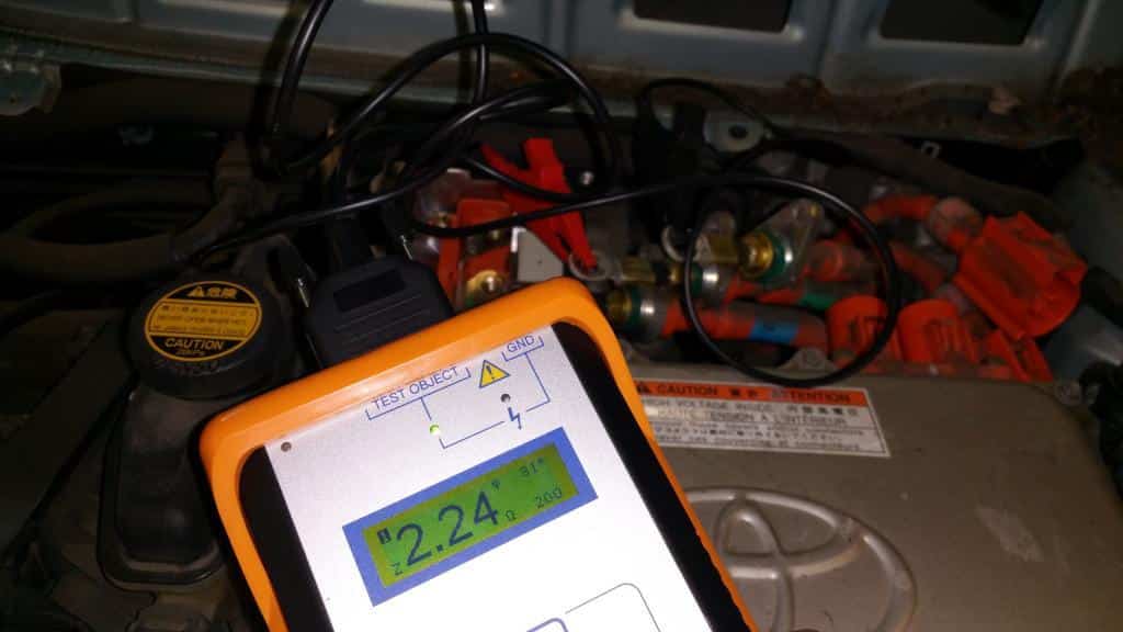
How do you interpret the results? Same as every other test — check to see if the phases are equal (within 5% of each other). The rotor’s magnetic field will affect the winding’s impedance. This can’t be eliminated, but it can made equal for each phase. This is accomplished by turning the rotor to obtain the lowest possible reading for each phase while it’s being tested.
Testing with this tool is quick and easy and it’s my go-to test for windings. The only downside is the cost. It’s a single purpose tool and it costs about $2500. This might be a little hard for most shops to justify given the relative infrequency of use.
Testing Using Current Ramp Analysis
This method is the most fun, and it also uses tooling most mechanics already own: a booster pack, an inductive amp clamp, and an oscilloscope. Do you like arcs, sparks, and bright flashes? Do you like using methods that no one approves of? Would you like to add a little danger to your life? If you responded yes to all of the above, this is the test method for you!
Here’s a quick summary of this test: use the booster pack to energize two phases while monitoring the current flow using an oscilloscope. I did not invent this test. Jack Rosebro (of Perfect Sky, a hybrid training company) is the person who suggested it to me, followed by a warning that he does not teach this in his classes because of the safety issues surrounding this type of testing.
Obviously, I must be less concerned with your safety than Jack is with his student’s safety. That said, if you burn yourself, blind yourself, damage your equipment, or cause other bad things to happen, Art’s Automotive is not liable. Like I said, this test is approved by no one.
I should also mention that Jack did not take credit for creating this test either. He wasn’t able to remember who came up with this idea, so if this was your idea or you were the first to adapt it to automotive use, drop me a line and I’ll give you the credit.
How does the current ramp test work?
Let’s talk about how this test works, and then about how to perform the test. An inductor resists changes in current flow. If you connect a booster pack between two stator phases, current will to ramp up. After around 50 ms (1/20th of a second) the current will level off. Remember, an inductor only resists changes in current flow. The current will eventually “funnel thought” the “restriction” caused by inductive reactance and there will no longer be any current limiting due to the inductance.
At this point the circuit will be purely resistive and its current flow can be calculated using Ohm’s Law. An important note about this test: the rotor’s magnetic field will affect the inductance measurement, so if the rotor is in the stator being tested, it needs to be positioned to have the same effect on each phase. Therefore, the rotor will need to be positioned before testing each phase.
With the All-Test Pro you can use tool’s display to position the rotor. How can this be done without a fancy tool? The easiest way is to line up the rotor is to energize the stator. Once energized, the stator is an electromagnet. The north and south poles will line up and the rotor will be perfectly positioned to test the phase that was just energized. However, since the MG2 is connected to the wheels, you’ll need to lift the car in neutral so the rotor can move.
What does a bad stator waveform look like?
So, what does good stator waveform look like? A bad waveform? Since we’re looking for imbalance, we don’t really need a specification, which is a good thing since there is none. We just need to know what differences there would be between a shorted winding and an intact winding.
A good winding will be a longer length of wire with more coils, since the current bypasses a portion of the wire on a shorted winding. The shorter the wire, the lower the resistance and inductance. The lower the resistance the higher the current. Therefore, a shorted winding will pull more current than a good winding. But we could have figured that out with an ammeter. Why are we using the oscilloscope? An inductor resists changes in current flow. Yeah, I know; I’ve said this a few times already, but I needed to hear this a few times myself before it sank in.
When the booster pack is not connected, the current flow is zero. When the booster is connected the current flow should be over 200A based on its ohmic resistance. 0A to 200A is a change, so the inductor will resist the change, but will quickly lose the pushing contest and current flow will rise to the level you’d expect based on Ohm’s Law.
So, what we’re going to look at with the oscilloscope is the rise time of the current to an arbitrary level of our choosing. That’s why we’re using an oscilloscope and not an ammeter. What we’re interested in is what happens during a very small period of time, a much smaller period of time that would be “noticed” by an ammeter.
Put on your thinking cap
Here’s a little mental exercise for you in case you’re starting to fall asleep. This article is already 20% longer than a typical trade magazine article and 5 times longer than the typical web article. Congratulations on your ability to concentrate for this long! You are a rarity in today’s world.
Here’s what I’d like you to consider: what would the current rise time look like on good phase compared to a shorted phase? Would the good phase rise time be less or more than a bad phase? Would a good phase have more or less impedance than a bad phase. After you have an answer, take a look at the waveforms below.
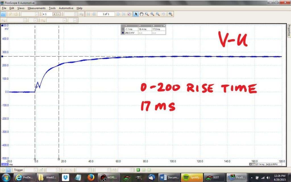
V-U Phases: 0-200A rise time = 17ms
The time it takes for the current to increase from 0A to 200A is 17ms. The current levels off at 268A Is this good or bad? There’s really no way to tell until you compare it to the others.
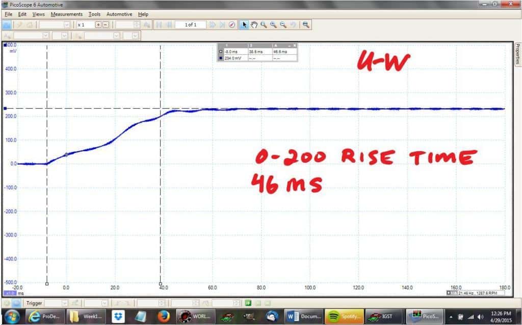
V-U Phases: 0-200A rise time = 46ms
0A – 200A rise time is 46ms, about 2.7 times longer than V-U The current levels off at 234A, about 13% lower than V-U
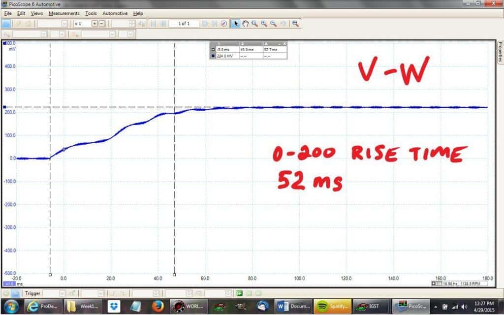
V-U Phases: 0-200A rise time = 52ms
0A – 200A rise time is 52ms, about 3 times longer than V-U The current levels off at 224A, around 16% lower than V-U
V-
So in summary: V-U 268A, 17ms rise, 0%/0% (base measurement) U-W 234A, 46ms rise, -13%/+270% V-W 224A, 52ms rise, -16%/+300%
The maximum variance between phases is 5% for All-Test Pro 31 testing, so I use the same specification for booster pack testing. I’ve seen 10% difference between phases with no trouble codes or symptoms (with both All-Test Pro and booster testing). A difference of 300% is without question bad, so this motor is toast.
Notice that there is also a smaller difference in the final current flow once the effect of reactance has subsided. When a winding is shorted, it has less resistance as well as reactance. I think the rise time is the more telling of the measurements. So, which phase is bad? Of course, it doesn’t really matter since the stator is replaced as a unit, but it’s good mental exercise.
A shorter rise time indicates less inductance. The fewer coils in the winding, the less inductance it will have. If a winding is shorted, it will in effect have fewer coils because some of the coils are bypassed by the short. In this case I reckon the U phase is bad.
We can’t test only one phase at a time because we have no access to the center splice. V-U is the worst measurement. U-W is the second worst. And V-W is the best. Since the U phase is included in both of the bad measurements, I might guess that the U phase has a coil to coil short, but I think that the U-W measurement would be worse if this were the case. My best guess is a phase to phase short between V and U. What do you think?
The Fix
There are three ways to fix this:
- Replace the transaxle with a new unit
- Replace the transaxle with a used unit
- Replace the MG2 stator
A new transaxle
A new transaxle is probably the best fix, but frequently people are not willing to spend this much money to fix their cars. By the time the MG2 fails, the car is no spring chicken, and an expensive repair may exceed the car’s Bluebook value. Some folks think of their Gen1 Prius as a collector’s item, and one day it no doubt will be. Other folks have a sentimental attachment to their cars or weigh whether to repair based on criteria other than a strictly monetary formula. For these folks, a new transaxle may be the best option.
A used transaxle
A used transaxle is not an option we offer here at Art’s; it’s more risk that we’re willing to assume. Sure, MG2 is the most common failure, and MG2 can be tested prior to installation, but a used part is still a gamble; there a lot more that can go wrong besides the MG2. Replacing the transaxle is a lot of work. If the used part has a problem and we need to replace it again, we’d be paying for the pleasure of repairing your car. We prefer to quote jobs that are as close to a “sure thing” as possible.
If you would like to explore used parts, check out Luscious Garage in San Francisco. It’s a great hybrid shop and installing used parts is one of their policies to reduce environmental impact. Replacing the MG2 stator has worked out well for us so far. Since the transmission we’re repairing is a known quantity, we start the project with a pretty good idea if there are any problems with the unit besides MG2.
A stator replacement
The first time we performed this repair we installed the MG2 as it came from the dealer, meaning we removed the transaxle, split the cases, set all the preloads with shims, put it back together and back into the car. This was not the best way to do the job. You can check this link if you’re interested why. Luscious Garage pioneered a better method which we’ve adopted. While this method should create issues with resolver calibration, it clearly doesn’t cause any sort of detectable problems.
Removing the transaxle
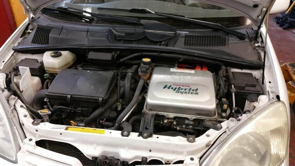
OK. Less text, more pictures.
Lets get started. First we’ll need to remove the inverter because transmission mount is located under the inverter and the MG2 cables are connected to the inverter.
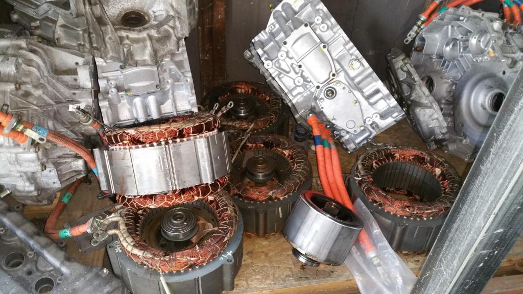
Crispy hybrid MG2 stator Winding
I’ll let you be the judge. Does it look like the stator was actually overheating, or was it just a sensor error.
Like I said earlier doesn’t really matter either way, the temperature sensor is wound into the stator winding and there’s no way to replace it without replacing the stator winding.
Where There’s Smoke
The stator winding off-gassing “painted” the stator cover black.
Design Flaw
We’ve seen this on every Prius transmission we’ve rebuilt. This is the oil pump output tube and the o-ring is pinched. If you check out the other Prius transmission repair article, you’ll see a picture that looks nearly identical to this one. I don’t think this is an assembly error at the factory. I’m guessing the o-ring is incorrectly sized or the crimped slot in the tube isn’t adequate to hold the o-ring in place. The stator cover has a nice chamfer on it, so I don’t think that’s it.
Stator Removed
The old stator is out.
New Stator
As you can see the stator is not available separately you can only buy the mg2 side of the transmission. If you check out our other article where we installed one of these, you’ll see that there’s a huge disadvantage to using the case. The rotating assemblies supported by the two halves of the transmission must be shimmed for proper end play. The shims are not readily available. Last time we installed the case like this it took 2 months to get all of them.
Measuring
In this picture I am measuring the hight of the rotor.
Stator cover Measurment
Here I’m measuring the distance between the edge of the case and the area where the rotor will be riding.
I also measure the depth between the transmission case and where the other end of the rotor will ride, but that was a difficult setup and I couldn’t get a picture of it since I needed both of my hands.
Choosing a shim
Next I’m measuring the shim to see if it’s going to be usable. Since I plan to install the stator cover that came with the new transmission half, I need to make sure that I’m not affecting the clearances.
It’s Going to Work
Luckily for me there was only a 0.002″ change in the clearance. This falls well within the specifications in the manual.
Hybrid Transmission Rebuild COmplete
All that’s left to do is put on the stator cover without pinching that pesky pump o-ring and will be back in business.