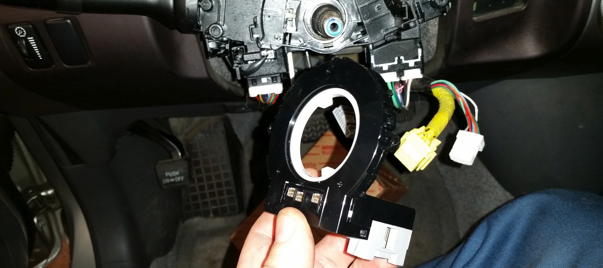
I can’t say I’ve ever seen one of these fail. Steering angle sensors (SAS) seem to be pretty reliable. However, the “clock spring” or spiral cable for the air bag, horn, and steering wheel buttons to do fail, and sometimes the SAS comes with the clock spring.
One day a car came in and needed a clock spring, and the new one came with an SAS, so I figured I’d take it apart and see how it works.

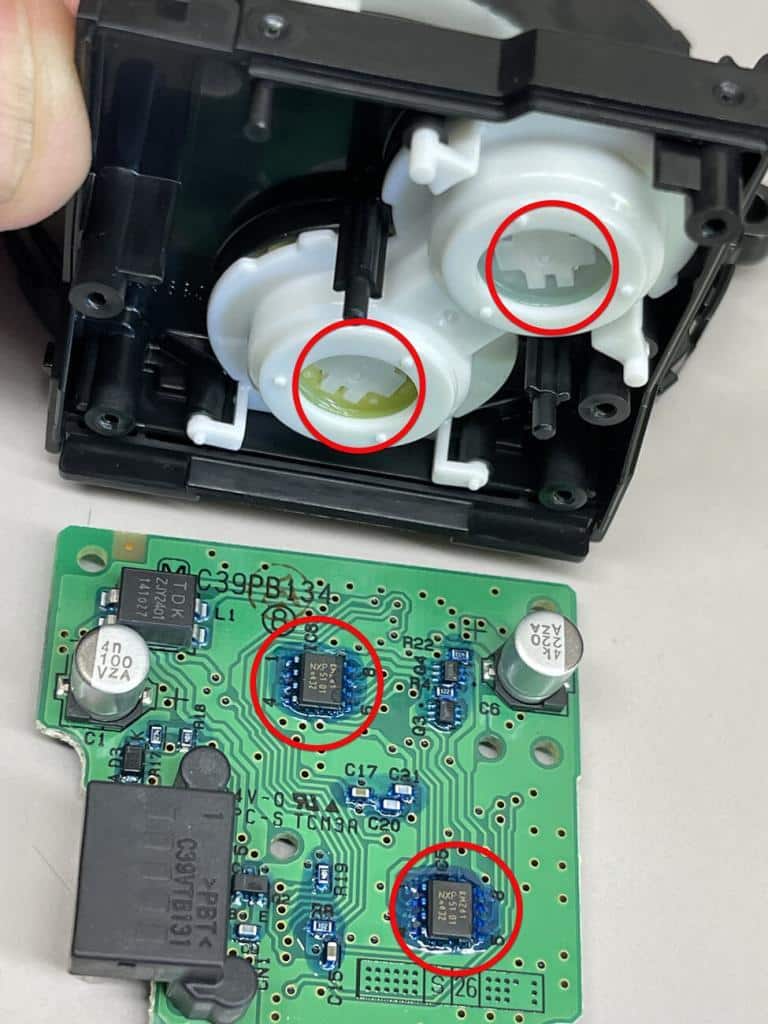
When the driver rotates the steering wheel, two dogs in the gear pictured to the left cause the gear to move with the wheel. This ring gear then turns a pinion below, and that pinion turns another pinion in the opposite direction.

The pinion gears are held in housing directly above two identical chips on the circuit board. There is no contact and there’s nothing that could be an optical sensor, so it must be a magnet sensor of some sort.
I have a card that will darken and lighten to show if a magnetic field is present. It’s for science education, but it’s handy for finding encoders in wheel bearings and in this case, checking to see if there’s a magnet in the gear. The gear doesn’t pull on a pocket screwdriver, so it’s certainly not a strong magnet.
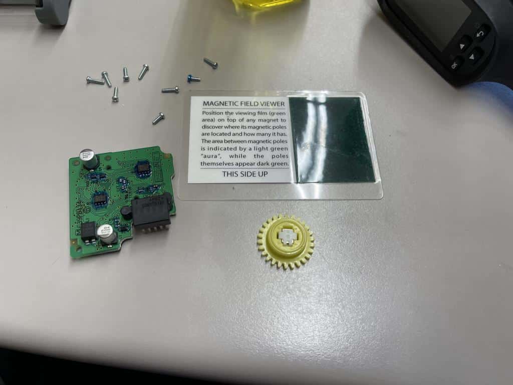
Sure enough. There’s a north and south in the center of the gear.
Surprisingly I was able to look the chip number up. I say surprisingly because a lot of times automakers custom order their chips and assign their own numbers to them, even when they are the same as commonly available chips. I’m not really sure why. It might be for IP reasons, or maybe they have their own system of chip function designation, or perhaps they want to make sure nobody starts repairing the devices.
Anyway, in this case there’s a standard chip number and if you punch it into Google you can get a datasheet or purchase one if you need it. The datasheet confirms that the chip is a “sensitive magnetic field sensor”.