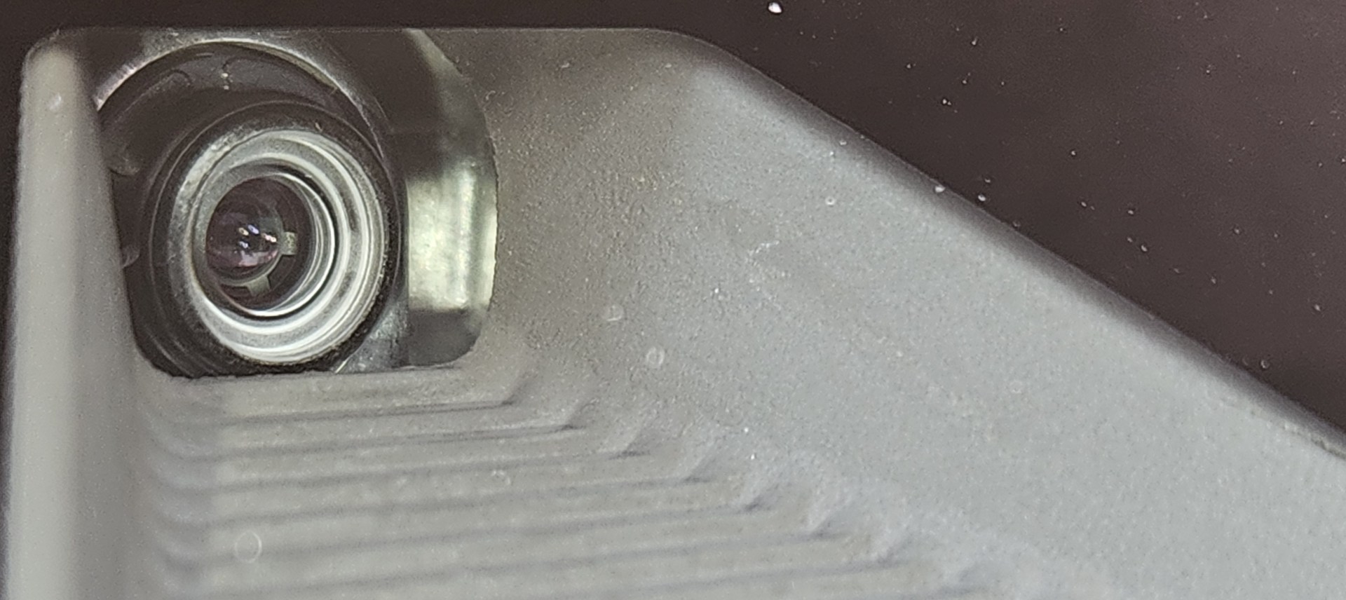
Replacement of the Honda multi-purpose camera (which is the one behind the windshield near the rear view mirror) is pretty simple, but unfortunately it requires a static calibration, which means you’ll have to pay an ADAS specialist like us to replace the unit for you. In the future I imagine that many of these units will calibrate dynamically, and therefore will be less expensive to replace.
If you live in or around Berkeley and need a camera replacement we’d be happy to assist you. Our labor prices are much lower than the dealerships, and frequently lower than other independent shops. Unfortunately the part is only available for from Honda, so whatever they charge is how much it costs.
In this article I attempt to diagnose and repair a Honda multi-purpose camera unit. I think I found the problem, but don’t currently have the skills to correct it. If you’re interested, read on.
Honda Multipurpose Camera Failure – U3000-49
Lately we’ve seen a lot of multi-purpose camera failures on Honda products. So far we’ve seen this failure on the Accords, Fits, Claritys, CR-Vs, and Odysseys. Typically the driver will report warning lights like LKAS, BRAKE, ACC, CMBS, RDM, etc. After scanning with the HDS, we find a U3000-49 (internal electronic failure of a control unit).
The diagnosis is pretty straightforward. According to the service manual we only need to clear the code and then confirm it reappears. If the code comes back after being cleared then we replace the camera.
In our view it would be pretty irresponsible to replace the camera without first checking powers and ground to the unit. Low voltage can cause all sorts of problems with electronic control units. A good control unit can set this type of code if the battery voltage is low, so we always do our due diligence and check to make sure the camera isn’t suffering from the digital equivalent of hypoxia.
Once we replace the camera we perform both static and dynamic calibrations. If you’re interested in that you can read this article about ADAS calibration.
Can the Multipurpose Camera be repaired?
So, can we fix this Honda Fit’s camera without replacement? I enjoy repairing electronic control units. Is both interesting to me and profitable, and it has the added bonus of being less expensive for our customers. After seeing a lot of Honda multi-purpose camera failures, I began to wonder if the units might be repairable.
Of course there’s always the concern about being sued if a repaired unit fails and someone blaming a collision on the failure. But when you think about this, it’s kind of ridiculous. The cameras already fail all the time, and they’re designed to shut off when they get too hot. ADAS (Advanced Driver Assistance Systems) are meant to be just that: driver assistance. The driver is ultimately responsible for driving the vehicle. But this is America and we love to blame everything on each other, especially when there’s money to be had.
So despite my concerns about legal liability, curiosity got the better of me and I decided to take one of the faulty units apart and see what I could find.
What FailED?
Initially I was very excited. I found a 220uF capacitor that tested at about 140uF. It was on the output of a 3.3 volt linear power regulator. But when I checked, the 3.3 volt output was absolutely solid. The bad capacitor was not causing the issue.
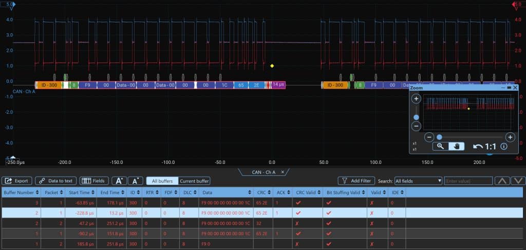
Next I checked the CAN bus output. The disembodied camera repeats the same frame over and over. The message is: F9 00 00 00 00 00 00 1C. What does that mean? I have no idea. I’m no network Guru. I assume the ID300 is the camera saying, “Hey, I’m the camera”. One thing that struck me is that the message never stops repeating. It seems like they would want it to time out after a while so it doesn’t continue spamming the network. But then again this is a broken unit, so it may not be behaving as it was designed.

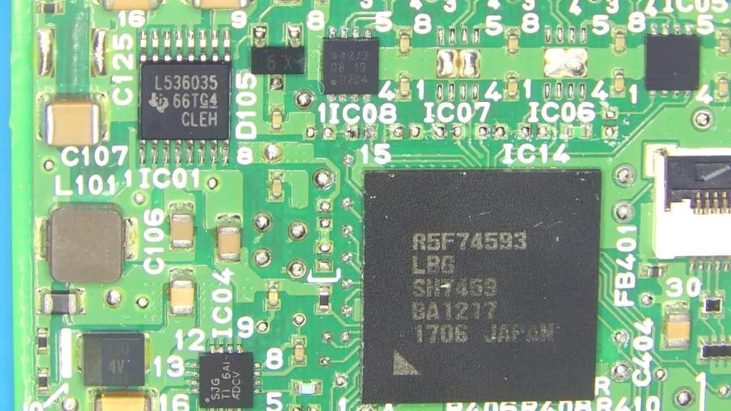
I traced the CAN high and CAN low terminals to the component labeled IC08. It’s marking is A42/3. Using the marking I was able to find a data sheet. It’s a high-speed can transceiver developed specifically for the automotive industry. Pins 6 and 7 are connected to the can bus. Pins 1 and 4 are connected to the MCU. Pin 1 is a transmit line (TXD) from the transceiver to the MCU. Pin 4 is a receive line (RXD) from to the MCU to the transceiver.

Transmit line doesn’t look good
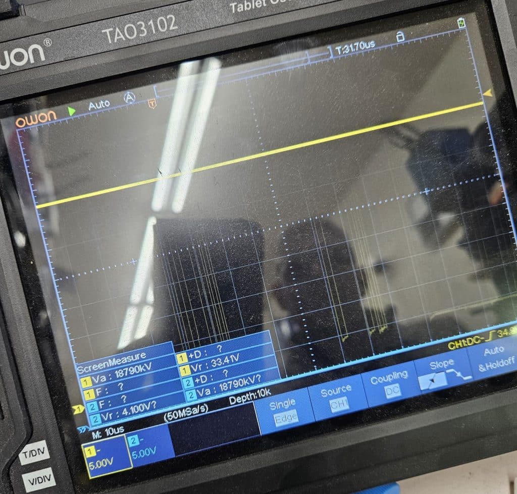
There’s a suspicious signal on pin 1 (transmit from the transceiver). At first I thought it might be high speed network traffic, but the doesn’t look like it to me. I could be wrong.
In order to determine whether the noise was coming from the CAN transceiver or the MCU, I desoldered a filter in between them and checked for the signal on both sides. The signal was coming out of the MCU, so I suspect the MCU is the problem. This is the line the MCU should be listening on. Even if the signal is good, why would the MCU be talking on its listening line?
I assume the MCU has all the programming that makes this unit run, so while it does appear possible to purchase a R5F74593 MCU, I wouldn’t have the faintest idea of how to go about extracting the programming from the chip (assuming it’s not so broken that it’s impossible) and transferring it to a new chip.
It looks like I won’t need to make any decisions about exposing myself to liability after all. I don’t think I can fix this.

If you know something about this sort of thing and want to share or tell me what I got wrong, I’d love to here from you!
Honda Multi-purpose Camera Replacement
So, for now it looks like we’ll be offering the same thing that every other ADAS shop and dealership offers, multipurpose camera replacement and calibration. If you live in Berkeley or any of the surrounding East Bay Cities, give us a call we’d be happy to help.
