Art’s Automotive offers advance Honda hybrid diagnostics and repair in Berkeley. We’ve been working on Honda vehicles since 1980, and Honda hybrids since the Insight was introduced in 1999. Complex electrical diagnostics have always been one of our strong suits, so it’s only natural that as hybrids got older and started to break, we added hybrid diagnosis to our list of services. Today we’re able to handle any hybrid diagnostic challenge and provide the following:
- Check engine & IMA light diagnosis
- Hybrid battery diagnosis and replacement
- Camera and ADAS sensor calibration & aiming
- Intermittent electrical faults
- Technicians with hybrid expertise

Follow along as we diagnose an intermittent hybrid system issue on a Honda Civic. This is a story about a P1560 – Electrical motor encoder fault. This article covers some advanced Honda hybrid diagnostic techniques, at least for their time. These days Honda hybrids use far more advanced systems and is our equipment more powerful. But the basics are still the same. Follow along as we diagnose and repair an intermittent electrical fault on a 2004 Civic Hybrid with trouble code P1560.
I’ll start with a little background, but if you already know about the Civic Hybrid design and why encoders exist, you can skip the next paragraph.

Why use an encoder for the IMA motor?
The Gen1 Honda Civic Hybrid included model years 2003, 2004, and 2005. It’s pretty unimpressive as far as its hybrid design. A low power motor/generator Honda calls the “IMA motor” is driven by an air-cooled inverter with power from a 144V NiMH battery. The IMA rotor is bolted directly to the crankshaft, so you might think that the crankshaft position sensor could be used to determine the rotor position. The problem with this is that the crank position sensor only works when the crankshaft is spinning. When the motor is stopped there is no signal from the CKP, and the inverter must power the correct stator phase when the engine is started from a dead stop.
There are a couple types of rotor position sensors that could give the motor control module (MCM) an “absolute” position while stationary. The first is called a resolver and is extremely precise, accurate, and robust. Toyota uses resolvers in all of their products. The second is called an encoder. It’s less precise, but good enough for the application.
A rare failure
In this article I’ll share some information about a 2004 Civic Hybrid that came in with an encoder code, which is a pretty rare occurrence. So if you’re curious about how the Honda rotor position sensor works, or have a car with a similar issue you may find this article helpful. To help folks searching with Google, the commutator sensor codes include P1560, P1561, P1562, P1563, P1564, and P1566.
How does an encoder work?
An encoder judges position by looking at ON/OFF signals, 0s and 1s. The IMA encoder has 3 “switches” and six possible combinations of ON and OFF: 001, 010, 100, 111, 011, 110. One rotation is 360 degrees, so I originally thought that the encoder was only capable of 60-degree resolution, which is pretty awful. However, the IMA rotor has many poles. I *think* there are 18 poles, but I’ve never actually checked. Anyway, if we take 360 degrees divided by 18 is 20 degrees. So, every 20 degrees a 360-degree electrical cycle is completed (a full sine wave). 20 degrees divided by the six encoder states is 3.33 degrees. So, I figure the resolution is around 3.3 degrees. I may be completely wrong though.
Encoder vs. Resolver
This encoder basically tells the MCM the the 18 rotor pole positions in relation to the 18 stator coil positions, which is good enough to energize the correct phase and move the rotor in the desired direction and probably cheaper than installing a resolver. A resolver has very high resolution. It can measure where the rotor is in 360 degrees down to 10,000 positions (0.04 degrees). Resolvers are also reputed to be indestructible. This is why I think the decision to use an encoder was probably based on cost.
HOnda Hybrid Diagnostic Information
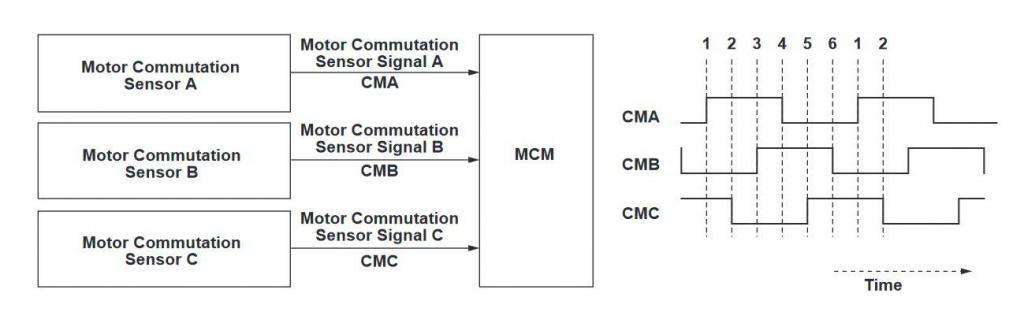
The Honda hybrid diagnostic manual has some useful P1560 information in the “Advanced Diagnostics” section. As you can see (above), the sensors generate a square wave. I assume these are hall-effect sensors since they has three wires each and they go high when close to a ferrous object. There are 6 protrusions on the flex plate that pass the 3 sensors.
Case history
This particular car was setting a P1560, but only very intermittently, creating problem for both the seller of the car and the recent purchaser. This was a car that had been fixed up by another shop and then sold to the current owner. The shop was taking responsibility for the problem and had been working hard to fix it, but the code would only set every 200 miles or so, making it nearly impossible to diagnose. Before they brought the car in, they had installed an entire IMA motor (with encoder) figuring it was the most likely cause. Unfortunately, even after this expensive guess the problem persisted.
P1560 Diagnostic procedure for The Honda Civic Hybrid
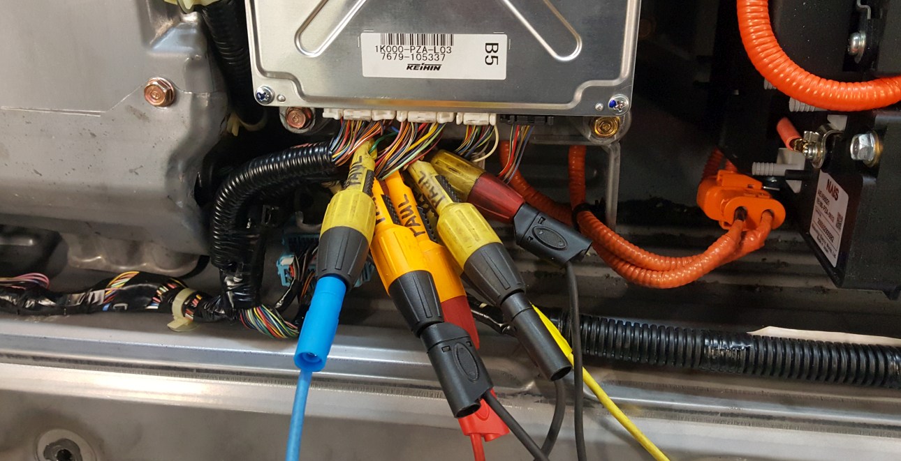
I figured the first step should be to look at what the IMA ECU was looking at: the voltage signal from the encoder. The best place to check is right at the ECU, so I can see any effects the wiring is having on the signal too.
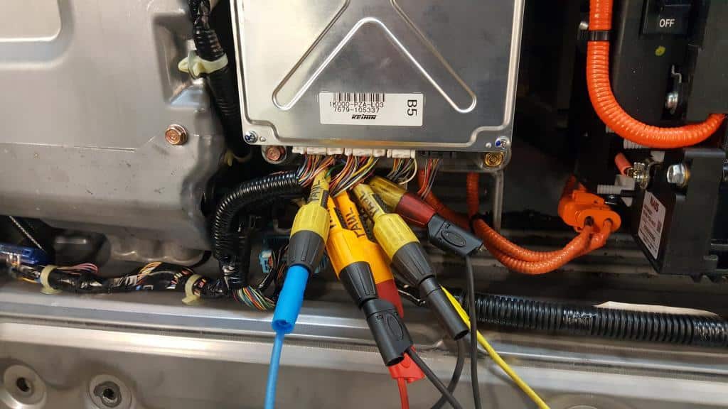
I love the Pamona piercing probes. Getting a reliable connection is critical to getting real results. Many mechanics freak out about piercing probes, “The wires are going to corrode!” I’m not worried. The holes are tiny and heal pretty well, it’s inside the car, and it’s California. Besides, I’d like to see someone try to get a reliable connection using this many back probes with gravity working against them. You’d be more likely to create your own phantom “faults” and spend hours chasing your tail.
Good encoder signals
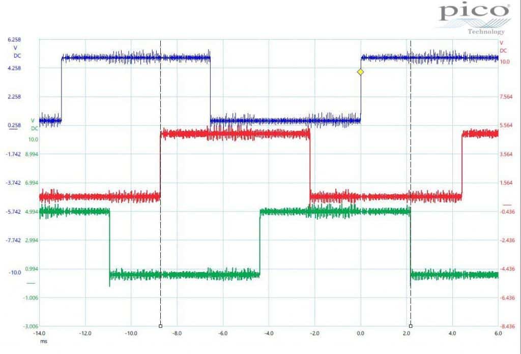
The waveform for the encoder looks pretty much exactly like the example in the manual. This isn’t surprising since the code isn’t resetting currently. The Picoscope records all the time. As you long as you stop the scope before the buffer is full, you can scroll back and view the data, so if we can get the car to act up, we can see what’s going on with the signal at the computer.
Inducing a failure
So how can we make it act up without driving 200 miles with the scope hooked up? Most intermittent problems are caused by a poor connections, sometimes inside a component, but most of the time in the wiring. I start off by tapping on the encoder with my “diagnostic hammer”. Not the big one I use on my bad days, but a tiny hammer I use create a little vibration in the hope will cause a symptom. Unfortunately, no symptom, so the encoder is either OK, or impervious to the rigors of the diagnostic hammer.
Bad encoder signals
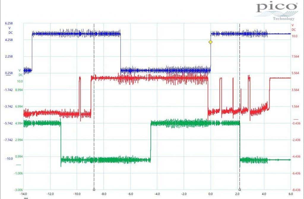
Next, I followed the harness while wiggling and jiggling. When I got to the connectors near the battery pack, which houses the MCM (Motor Control Module), I finally captured the glitch. The red trace in the middle of the screen clearly isn’t normal.
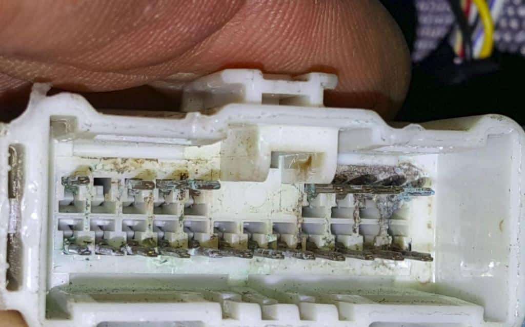
The conclusion Of Our Diagnosis
A quick peek into the connector and the problem is obvious. A bit of careful corrosion cleaning and deoxidation and the connector can be wiggled and jiggled with no signal dropouts. The P1560 has been fixed.
By the way, there are commercially available tweezers with diamond grit abrasive on the tips that can be used to clean male terminals. They’re about $50 and are too course for my liking. A pair of cheap tweezers, a couple drops of super glue, and couple small bits of sandpaper and you have a tool that works even better.
Honda Hybrid Diagnostic in Berkeley
Thank you for taking the time to read about our Honda hybrid diagnostic adventures! Whether you’re in Berkeley, Oakland, Albany, El Cerrito, Orinda, Richmond, or anywhere else in the East Bay, we’re available for your Honda hybrid diagnostic needs. Call if you have any hybrid questions or to schedule an appointment.
Other articles you might like:
Honda Civic won’t turn off
Prius transmission repair
Highlander hybrid inverter repair
Prius P3125
Prius electric motor replacement