I’m going to start this page by giving credit where credit is due: Hobbit did the initial investigation of the 2004-2005 Prius Multi Function Display (MFD) communication failure issue, and everything I’ve done so far has been built on the work he has shared on his web site.
Please don’t email or call to ask if you can send us your MFD for repair:
1. We don’t have a test bench set up to simulate a Prius, so we need to have the car here for testing.
2. We aren’t set up as a mail order repair service, and dealing with emails & shipping would be a pain.
3. We have may not have perfected the repair procedure yet.
UPDATE: I should have put this link in a long time ago. There’s a guy in Indiana who repairs Prius multi-displays and doesn’t charge a lot. He’s also better at it than I am. We’ve referred a lot of customers to him and his track record is very good. We’ve only seen one unit with a problem and he repaired under warranty it without any hassle. You’ll need to deal with him directly, since we don’t get in the middle of it. He even has DIY instructions for removing the multi-display from the dash if you’d like to tackle it yourself. If not, we’ll remove it for you and re-install it after it’s repaired. His business is called Auto Be Yours.
This is the story of an MFD that is in for it’s second repair. We fixed it once, but it only worked for a month. Since the MFD is a $4000 part, it’s probably worth spending some time to determine whether a reliable repair is possible, so we gave it another go. I attempted to repair a damaged solder connection using a reflow station on the first try. This time I’ve re-soldered the damage using a soldering iron, and I also by-passed the suspect area with “green wire”.
Warning: Even though there is only 12V going into the MFD, LCDs create very high voltage using a step-up transformer. This is the story of what I did, not instructions for you to follow step by step. If you kill or maim yourself, don’t blame me or Art’s Automotive.
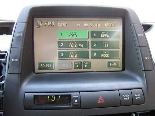
The symptoms for a failed Prius or Highlander MFD are:
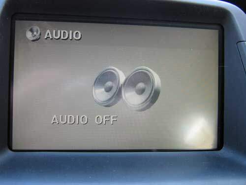
The display may have a message saying the audio is off, even though the radio is on.
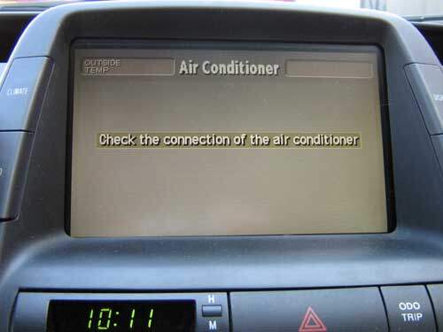
There may be no way to control the heater or air conditioner from the multi-display. Instead of the normal climate control screen there may be a “Check the connection of the air conditioner” message displayed
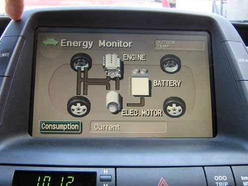
There will also be no information on battery state of charge or power flow. If the vehicle has navigation, there will also be problems with connecting to the navigation unit.
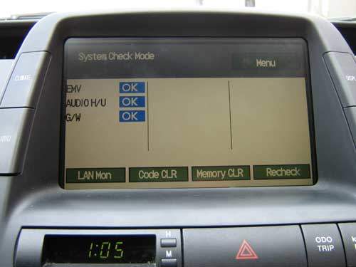
Self diagnostic function
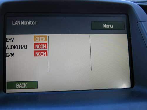
The LAN monitor says pretty much the same thing. The EMV (MFD) now says CHEK (which means there should be a code stored), but I couldn’t get it to give up any codes while it was broken. Maybe I was just being too impatient. The MFD was moving very slowly. It seemed to be spending most of its cycles trying to establish communication, and was very slow to respond to user input.
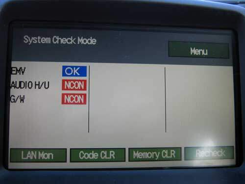
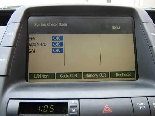
When you enter the System Check Mode (press & hold the INFO button on the side of the MFD & turn the headlight switch to the parking light position three times in a row, starting & ending in the OFF position), you’ll see a NCON (No Connection) warning for the AUDIO H/U as well as G/W.
The AUDIO H/U is the stereo.
G/W stands for Gateway. The Gateway ECU is the computer that allows the 3 busses (AVC, BEAN, & CAN) to talk together.
EMV is OK. What’s the EMV? It’s the multi-display. Why not just call it MD instead? I have no idea.
Basically, this means the MD can talk to itself, but not to anyone else.
In the Vehicle Signal Check Mode does not rely on information from the bus. (The bus is a two wire data path between control units). The MFD monitors these items directly.
IG is “Ready”.
PKB is the parking brake.
TAIL is the headlight switch position.
ADIM/TCAN is the MFD dim/bright status (based on the headlight switch position it seems).
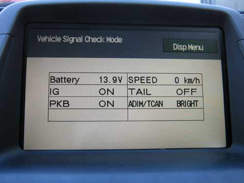
Since the headlight switch is used to enter diagnostic mode, its position must be monitored without using the bus.
The speed is likely used for function lockout based on vehicle speed. So if you are looking to hack this, so you can drive, dial, & crash, this is probably a good place to start.
Why the parking brake? I’m not sure. I do know that Toyota locks out some scanner utilities (like brake bleeding) if the parking brake is not set. So I’d guess that the PKB signal is responsible for some sort of lockout.
Anyway, all of the stand alone multi-display functions seem fine. The problem is only with its connection to other control units.
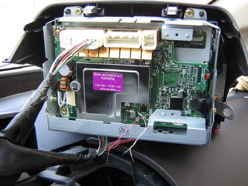
Removal
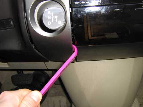
Time to yank it out. The Prius has a well designed dash. My handy KTC plastic pry bar is all that’s needed to remove all of the covers. You could use a sturdy tongue depressor, a taped screwdriver, or whatever.
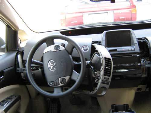
Here I have the covers removed. Well, removed enough.
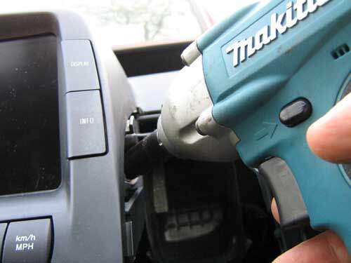
The multi-display is held in place with only two bolts. There are also some retention clips, but they’ll release if you just pull straight back.
Testing
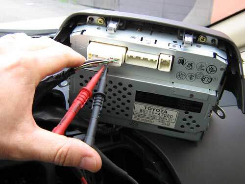
First I check the resistance on the AVC bus. The terminating resistor for the AVC bus is in the stereo. An open would indicate a break in the wires to the stereo, or an open resistor in the stereo. Without the terminating resistor, the data signal gets big and sloppy. The control units will talk and listen, but have trouble hearing what’s being said, and may not be able to communicate at all. The resistance should be about 60 ohms because each resistor is about 120 ohms and they’re wired in parallel.
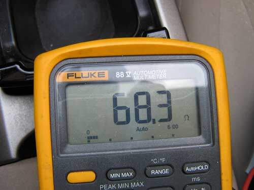
68 Ohms. Close enough.
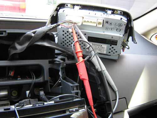
Next I hook up a scope. What will I be able to tell from this test? Not a whole lot. Mainly that data is being sent on the bus, but I can’t make sense of the 1s & 0s, so I won’t know what it means.
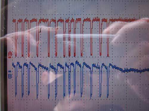
Lotsa squiggly lines. Somebody’s talking on the network. At least one node can be “heard” at this location.
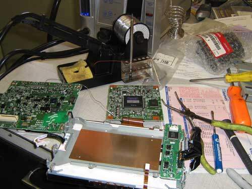
Repairing the multi-display
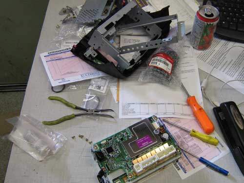
Time to tear it up. This is my third MFD disassembly, so it’s pretty easy now. I know were every connector & screw goes. The first couple times my desk looked like an operating theater with bags & bins & labels. Now I’m getting comfortable and just lay it on top of all the work that has piled up on my desk while I’ve been working on the Prius. Hopefully OSHA doesn’t notice my open can of V8 🙂

The connectors are very small & delicate. If you just tug on the plastic connector, like you would in the normal sized world, you may break all of the solder joints where it mounts to the board. A better way is to gently insert a small screwdriver into the connector joint and twist. That way the force is applied to the plastic connectors, not the solder joints or wires. I found this out the hard way while fixing one of our LCD monitors here at the shop. I had to go back in to fix the problem I created after fixing the problem it originally had.
I relied entirely on Hobbit’s findings for the repair of the first multi-display. In other words I assumed that the problem with my multi-display would be the same as the problem he found with his.
This time I have a plan this time. Rather than assuming the surface mount connector is at fault, I’m going to solder test leads on either side of the connector so I can check the signal on either side of the connector, and know for sure the connector is where the break is.
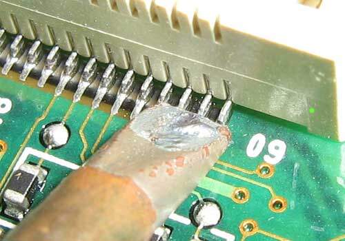
This is the surface mount connector that causes the trouble. As you can see, it’s tiny. This picture gives you an idea of the scale. This is a standard 2mm soldering iron tip (cold). As you can see, it’s over four pins wide.
Thanks to the SMD soldering tutorials on Spark Fun and some practice, I decide that I’m not afraid to try soldering my test wires right to the tiny pins.

A couple months ago, during my first repair attempt, I had used the reflow station because it was easy for me. It’s a lot like plastic welding, and I’m pretty good at that. I had wanted to use the soldering station, but after some practice on an old motherboard, I realized I did not have the skill to solder on a $4000 component yet.
This time I had more experience with a 1mm cone tip soldering iron & solder wick, so I was able to solder the small pins well enough.
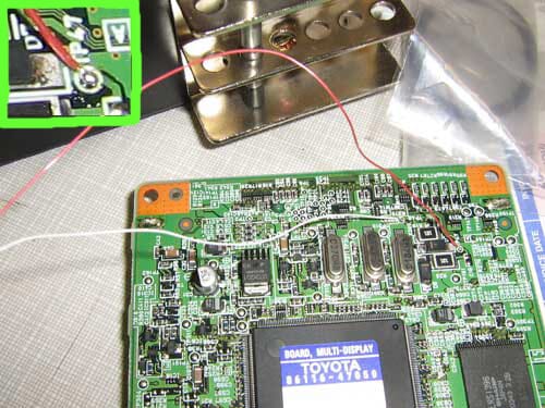
I’ve been practicing soldering very tiny stuff, and my skills have improved. First I soldered two leads at TP47 & TP48 on the “small board”, just like Hobbit did. Hobbit figured TP47 & TP48 were “Test Points” 47 & 48, and found that they were an easy place to access the AVC bus on the small board
Now I’ve got one red wire & one white wire coming from pins 60 & 58 on the big board connector, and another red & white set coming from TP47 & TP48 on the little board. I’ll be able to “see” data on either side of the connector, and I should be able to tell whether the problem is between the external connector and the big board connector, or between the big board connector and TP47 & TP48 (which are sort of near the little board connector). If the connector goes open, I should see data that looks “unterminated” on the small board side and normal data on the big board side
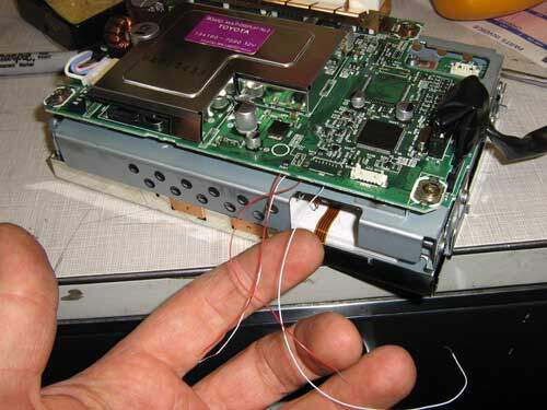
The unit is back in the car with the rear cover off. The test wire sets are dangling out the back for easy testing at the first sign of trouble.
This is looking promising!
All of the multi-display functions are working perfectly! After a little shaking, smacking, vibrating, and connector tugging, I’m convinced it was probably fixed by the re-soldering. I think that adding 60/40 solder will be a better solution than using a hot air gun to re-melt the old RoHS solder.
If you like the idea of fixing MFDs or electronic parts yourself, I’d recommend the following resources.
Hobbit’s website (http://www.techno-fandom.org/~hobbit/) has a ton of Prius related stuff, including the original MFD repair page.
Spark Fun (http://www.sparkfun.com) They have SMD (Surface Mount Device) soldering tutorials, kits to build for fun & practice, You Tube soldering demonstrations, etc.. They’re sort of like HeathKit from the 70s. Lots of fun, if you like that sort of thing.
Toyota’s information site (http://techinfo.toyota.com). Training courses and of course vehicle specific information.